selenium diode
diagnosis &
replacement
selenium diode
diagnosis &
replacement
We live in a historical period in which the amount of information is enormous; unfortunately, in some areas, this abundance leads to confusion and only serves to render the information itself useless. For me, this also applies to selenium diodes. This component, which we often find in devices from the 1950s, 1960s, and so on, is now obsolete, but—and this is particularly important—it appears to be carcinogenic. On its own, the component is harmless; however, when it burns, it generates toxic smoke that is harmful to our health. The average lifespan of this electronic component isn’t particularly long, and those that have survived to the present day are unlikely to be in good working condition. Electronically, it is very inefficient and dissipates a large amount of energy as heat… heat that increases progressively as it degrades until the temperature causes it to emit a lot of smoke and burn. As for selenium, I looked for more information but, as I mentioned earlier, I found conflicting reports, and I even saw that it’s used in some therapies targeting cancer cells. It’s clear that oversimplifying information can lead us to view elements as belonging to a single category, and as a result, we mistakenly attribute both negative and positive characteristics to elements that are actually very different from one another. In the diodes in question, I believe selenium is present as an ’oxide‘ and is therefore chemically different from pure selenium. I will therefore not delve into something I have not yet thoroughly researched, and—given the low cost and negligible impact of the component itself—I prefer to replace it with silicon components, which are undoubtedly safer and more efficient. Selenium was discovered in 1817 by Jakob Berzelius, and in 1920, German scientists discovered that by layering sheets of selenium with sheets of another metal, current could flow through the various layers in only one direction. In the past, therefore, diodes were produced by coating aluminum or steel foils with a thin layer of selenium. In this way, at that time, it was possible to rectify alternating current, converting it into direct current without the use of a rectifier valve… and thus achieving significant cost savings.
Cost savings, less space occupied, the absence of a base and therefore the saving of another component, voltage drop that went from 25-30 volts of a tube to 5-10 volts of the selenium diode... and so this diode was mounted everywhere: radios, TVs, amplifiers, switchboards, etc., etc.
In 1960, the first silicon diodes became available, and selenium was classified as toxic and carcinogenic (see EPA link). Furthermore, it became apparent that as these diodes aged, their operating parameters worsened, significantly lowering their output voltage. This anomaly made devices incapable of operating at the bias voltages calculated by the designer.
For all these reasons, even if the equipment in question is still working properly, it is advisable to replace these diodes; all the more so if you are restoring old equipment that has been out of use for a long time, it is imperative to proceed with the replacement.
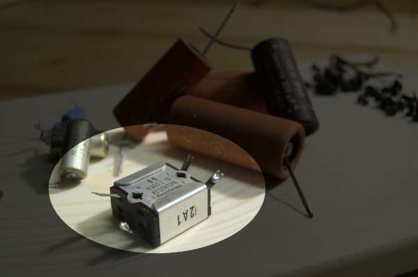
Replacement
The replacement with a silicon diode must be done correctly and various aspects need to be considered.
Modern diodes have extremely high peak currents and, when connected to a filter capacitor that acts as a short circuit when discharged, deliver a significant current capable of causing damage in some cases. Furthermore, silicon diodes, dissipating less current, have a higher output voltage and can therefore alter the bias voltages of other components. It is therefore necessary to place a resistor in series with the new diode for the dual purpose of limiting the inrush current and dissipating the excess voltage, bringing it back to the design values. Old selenium diodes, as well as rectifier tubes, self-dampened current peaks and therefore did not stress all downstream components.
Alternating current, whether it's the 220 volt mains voltage or the output of a transformer (12, 24 volts, etc.), when rectified and smoothed with a suitable capacitor, is at a higher level by a factor of 1.414.

For example, a rectified 220V AC will become 220 x 1.414 = 311 volts; similarly, a 24V AC will become 24 x 1.414 = 34 volts. This is because the capacitor will try to level the voltage at the peaks that are created (Vrms); the resulting DC voltage will be higher than the corresponding AC voltage. This happens for both silicon and selenium diodes. However, as mentioned, the latter generate a voltage drop that is 5 to 15 volts higher than their silicon counterparts.
To correctly calculate the resistor to place in series, you'll need to know the amount of current the circuit draws. For example, if we assume we want to lower the voltage by 10 volts and measure a current draw of 50 mA, we can then use Ohm's Law to calculate the resistance value: 10V / 0.050A = 200Ω.

The resistor we placed in series, to dissipate those 10 volts, will produce heat; therefore, it will be necessary to calculate the correct watt rating of the resistor. We could then use the formula to calculate the power: P=V^2/R
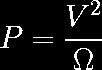
… in our case 10^2/200 = 0.5 watts. In this case, it will be convenient to conservatively choose a 2-watt resistor, as the 0.5 watts is the dissipated power, and a 0.5-watt resistor would burn out immediately while, probably, a 1-watt resistor would overheat. Therefore, after calculating the power, it is advisable to double or quadruple the value to choose a suitable resistor.
Which diode?
Silicon diodes are not, clearly, all the same. What type of diode should be used? The answer to this question clearly depends on analyzing the circuit in which we will be inserting it, and while it's true that any diode we use will perform its task, it's also true that using the most appropriate one will yield a better result. For example, in the audio field, it's particularly important that the diodes inserted do not generate noise that would inevitably spill into the amplified signal, creating hiss. In this case, it's preferable to use fast diodes, Schottky diodes for instance, which will cause fewer problems. Incidentally, if the filters following the voltage rectification stage are well-designed, the type of diode used is relatively unimportant, as the noise will be filtered out. However, I find it useful to emphasize that a diode can be a source of noise and therefore an element to consider if problems arise.
In my tests, I've been able to verify that in some amplifiers, installing a classic diode bridge increased the AC hum and the diode noise was audible and annoying. I then designed a very simple bridge built with suitable diodes, capacitors in parallel with them to further attenuate, and