g-221-a
audio &
vacuum tubes
AMPLIFIERS
AUDIO &
vacuum tubes
the restoration
jealous
g-221-a 12
The G-221-A is a Geloso amplifier built in 1960 in Milan.
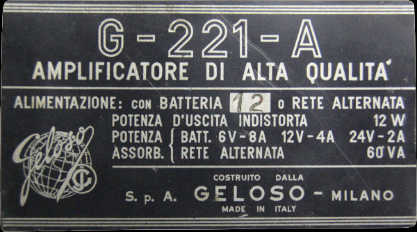
The musical output power is 12 Watts and the absorption is about 60VA, as can be seen on the product label on the side.
The unique feature of this machine is that, in addition to AC power from the mains (220v – 160v – 140v -125v -110v), DC power is available using a 6-volt or 12-volt battery. The choice of DC supply voltage configures two different products: the G-221-A 12 and the G221-A 6, where the last number indicates the DC supply voltage.
This is because, as we will see later, some details change for the two voltages, and in particular, the wiring for the filament power supply and the model of the asynchronous vibrator, which is the 1463/12 for the 12 volt and the 1463/6 for the 6 volt.
The valves mounted are 4:
- 12AT7 a dual triode in which the first amplifies the micro signal and the second amplifies the phono input
- 12AX7 that is to say the common ECC83, a double triode called to drive the two output tubes in Push-Pull mode and therefore as a phase inverter
- 6V6 A power tetrode in a Push-Pull configuration
- 6V6 … evidently the second section of the Push-Pull
My specimen
For this model, I decided to create a stereo version, so I searched for two units to be able to work them in this mode, thus obtaining a 12+12 Watt stereo amplifier... and let's say that a 24-watt tube amplifier is starting to be very interesting because we would be using a quartet of 6V6 in PP whose musical gifts are warm and powerful.
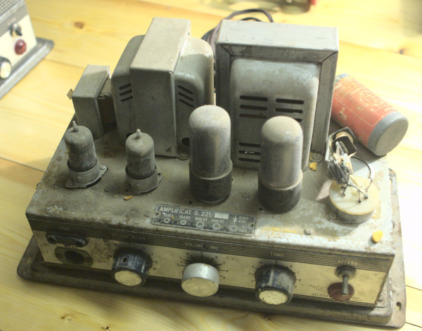
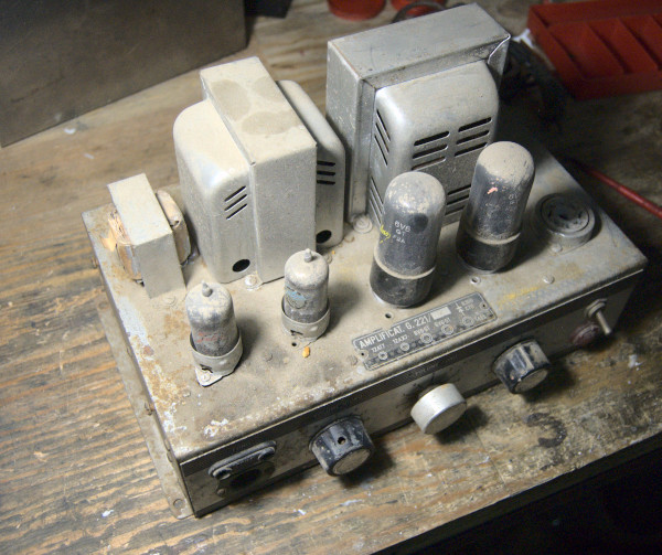
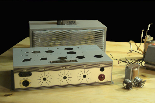
Let's start with the aesthetically worst example and we immediately notice that it shows all of its 62 years and, probably, it has found itself in a particularly humid situation in recent times.
Traces of moisture and rust are visible on the chassis, screws are damaged, debris and dirt are present; a knob has been replaced and the asynchronous vibrator is damaged. The 4 tubes are still the original ones, all branded Geloso, and therefore we will measure their characteristics to assess their condition and efficiency.
A look inside
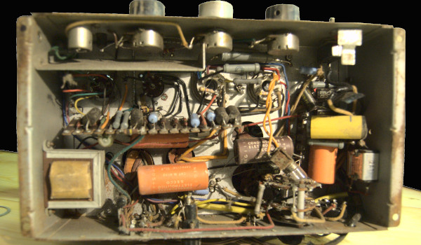
To understand the amplifier's actual condition and assess whether it's suitable for an accurate restoration, we have no choice but to take a look inside. Well, all the components are original, and there are no signs of clumsy repairs or tampering; the large electrolytic capacitors have stickers glued on, and if this unit had experienced flooding (which I didn't rule out beforehand), I would have found them detached and full of dirt. Internally, however, apart from the layer of dust accumulated over the last 60 years, the amplifier appears to be in good condition and I would say it has never undergone any repairs.
The diagram
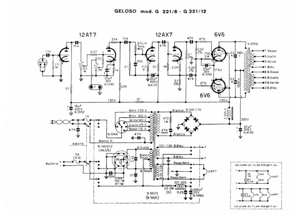
A quick look at the diagram, a document that will accompany the entire restoration and allows for a thorough understanding of the device. In essence, there is nothing particularly special... in the lower part, there is the power supply section where on the left you can see the mains or battery connection. For the mains, there is first the selector that allows you to choose mains/battery and then the voltage changer that selects the correct primary in the transformer. For the battery, however, after the selector, there is the non-synchronous vibrator which vibrates a reed at 100Hz and serves to enable and disable the passage of direct current in a dedicated primary of the power transformer; in this way, an EMF is created which I will find on the secondaries; I will elaborate on this topic later as it is damaged! On the right side of the power supply section is the diode bridge (which will be replaced regardless, and I will explain why thoroughly) for the anode voltage, and further down, the filament ignition voltages. It should be noted that in battery operation, a filter composed of inductor 321-005 and the two capacitors of 0.25 and 200 uF has been added... this is probably to filter the voltage generated by the non-synchronous vibrator, which evidently cannot generate an alternating voltage that is sufficiently stable and clean, and in any case, has a trapezoidal rather than sinusoidal waveform.
The signal then passes through the filter inductor Z305R to the actual amplifier where, from the left, you see the first double triode 12AT7 which is responsible for pre-amplifying the weak microphone signal and the second for handling the phono input. Here you can also see the control potentiometers for the microphone and phono volume... from this, it is also understood that the two channels do not exclude each other but are mixed on the grid of the second triode of the 12AT7.
Following the second double triode... 12AX7 which has the tone control potentiometer at its input (which we will analyze thoroughly later) and the double inverted signal at its output to drive the two final tubes. In this case, therefore, this second triode functions as a phase inverter.
Finally, the two finals 6V6 In a push-pull configuration that discharges all their power onto the final transformer, from which multiple secondaries were derived to allow the user to handle loads with different impedances. In reality, normally, several loudspeakers were connected to the output, and therefore it was necessary to try to connect them in such a way as to have a resulting impedance that allowed the best power transfer from the amplifier. This is why we find different impedances... depending on the number of loudspeakers connected (in series or in parallel, or even mixed groups) and the length and cross-section of the cable, the most appropriate output was chosen. The possible combinations are 16 and range from 1.25 ohms up to 500 ohms.
Let's start

And here's the chassis, more or less as it was found 60 years ago in Milan.
In this case, I proceeded with a rather aggressive sandblasting to remove both the remaining paint and the traces of rust. This work was, clearly, also done on the other part of the frame, the one that is mounted above to protect the valves.
Geloso used a hammered-effect paint for their amplifiers, an effect that gives an ‘industrial’ look. This type of paint also has another purpose... the sheet metal used is not free of micropores and, probably at the time, they couldn't find anything better cheaply, considering that the goal was to create a robust machine at the expense of aesthetic beauty. I therefore believe that this hammered-effect paint also served to mask the imperfections of the sheet metal used. Finding the same paint today would also be possible, but I prefer to proceed with a glossy finish, knowing that I will have to work to ‘recover’ the imperfections of the metal.
I will then proceed with a two-component spray paint, a RAL 7001, and then a protective clear coat.
After the first coat of glossy gray, all the signs and imperfections of the sheet metal are evident and will need to be corrected.
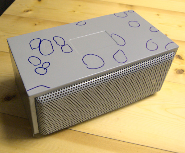
Here are two images of the shelter... on the right as it was, and here at the top after sandblasting and before the first coat of paint. I have marked all the porous areas that require correction before the subsequent coats.
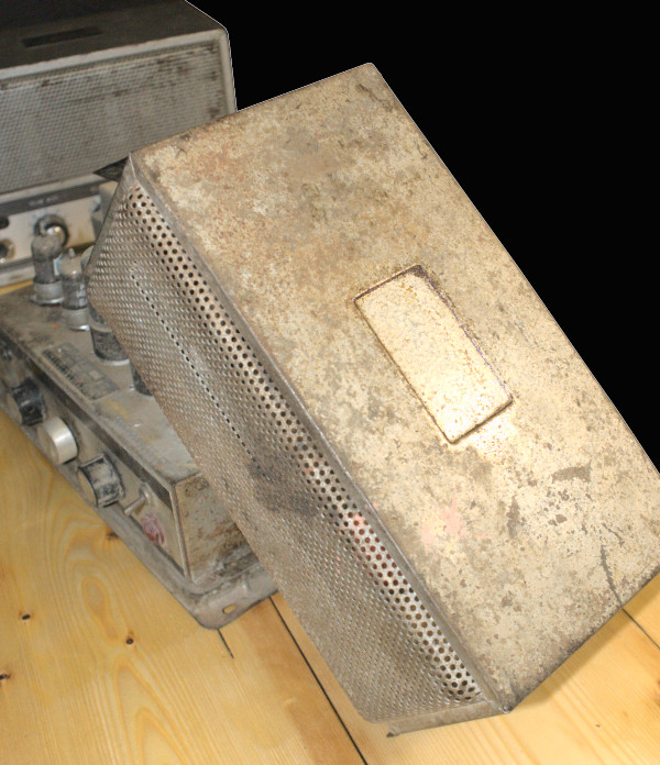
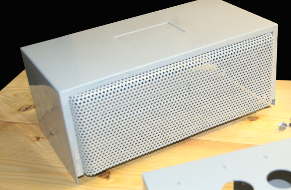
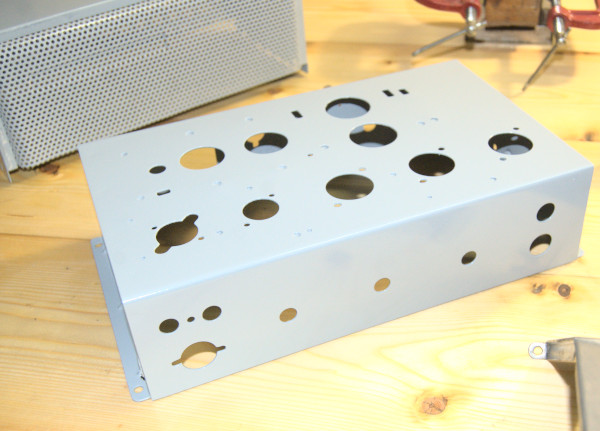
And here is the result after a few coats of grey. In fact, the paint covers very well even after just one coat, but wanting to follow the philosophy of ‘it must last a long time,’ I wanted to give a certain robustness to the paint layer, which, however, will be further protected by a few coats of glossy clear coat.
Now that the base is ready, it will be necessary to proceed with the assembly of the parts, but each one will have to be tested and measured to verify correct operation and avoid future unpleasantries. We will therefore focus our attention on the two transformers, the power supply and the output, the impedance adapter. These are probably the most important components, and fortunately, they were well-built by Geloso. In fact, this company not only produced radios and amplifiers but also manufactured all the necessary components in-house; some claim that the output transformers were purchased abroad. Indeed, it is not improbable that this may have happened for a certain period. What I notice is that this is mounted with an insulating paper on which I can read unequivocal writings that lead me to believe, without much doubt, that it is of Italian construction and that it was actually produced by Geloso.
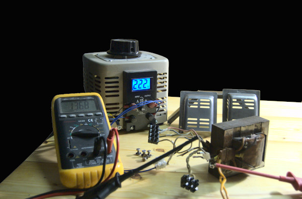
For the power transformer measurement, I used a Variac to gradually increase the voltage and check for any problems. Under no-load conditions, the voltages are:
- White / Blue 13.6 volt
- Red / black 7.0 volt
- Orange / Orange 275 volt
- white / red (110 volt) = 7.8 Ω
- white / yellow (125 volt) = 9.5 Ω
- white / green (140 volts) = 11.5 Ω
- white / blue (160 volt) = 16.0 Ω
- white / black (220 volt) = 30 Ω
- yellow red / red (vibrator) = 0.9 Ω
- orange / orange (anodized) = 70.5 Ω
- white blue / white blue (12AX7 filaments) = 13.6 Ω
- Red black / Red black (12AT7 filament) = 7.0 Ω
Output transformer - TU
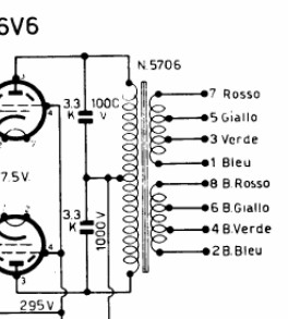
Here beside, for convenience, I am including the diagram of the transformer unit. Analyzing the diagram, it is clear that the primary has two sections connected to the anode, and a center tap connected to the negative of the diode bridge and, via the 32uF capacitor, to ground. It's the typical primary for a Push-Pull.
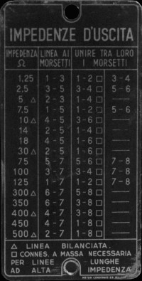
The secondary, on the other hand, needs a bit more thought: in fact, there are two, whose terminals are 7 and 1 for the first and 2 and 8 for the second; these two sections have intermediate taps, 5 and 3 for the first and 6 and 4 for the second. From the plate on the back of the device, we read that if we connect terminals 1 and 8 together (and thus put the two secondaries in series) and take the signal from terminal 7 and terminal 2, we have an impedance of 500 Ω... this is clear... in fact, we use both secondaries completely. By connecting the terminals according to the table shown and taking the signal from the terminals indicated on the same table, we obtain the 16 combinations that allow us to adapt the impedance of the secondary to the load we will connect. So, the practical case today is an 8Ω speaker, and therefore we will choose the closest value from the table... which is 7.5Ω. In this case, the signal will be taken from terminals 1 and 5, and two pairs of terminals will need to be connected together: 1 and 2, and 5 and 6.
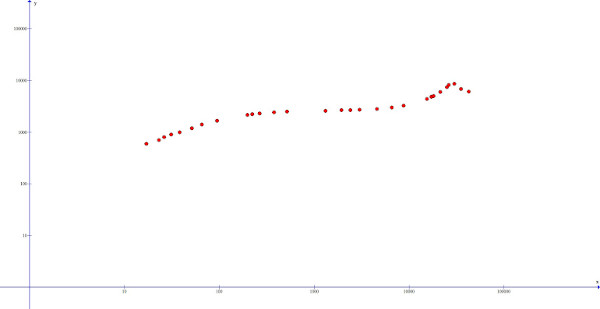
For a slightly more in-depth discussion on the measurement and testing methods of an output transformer (TU), I refer you to the technical section here. For now, it is sufficient to know that to verify the correct operation and quality of the transformer, we will place a 500Ω load between terminals 7 and 2, and a bridge between 1 and 8 to check the entire secondary. I will then proceed to measure the reflected impedance of the secondary at different frequencies (the classic range of audible frequencies... and a bit beyond) using an impedance meter, drawing a logarithmic graph that will describe the TU's response curve.
This way, a test will be performed qualitative and functional (even if summary) of the transformer and I will be sure that, once reassembled, it will not give me problems.
And here is the graph showing how impedance varies with frequency... I took the measurements starting from 17Hz up to 42.5KHz. It should be considered that humans can hear sounds from 20Hz to 20KHz (when young), but it is undeniable that inaudible high frequencies can still influence lower frequencies. It's also true that some people can hear sounds even beyond 20KHz. Anyway, since it's free, there's no harm in pushing a bit further, and as clearly seen in the graph, the transformer reaches 8kΩ at 27KHz (so beyond the audible range, before coming back down). Remaining within the audible range, at 21KHz it's at 5kΩ... exactly what's needed for the 6V6 (this is the measurement for the half winding... the total is clearly doubled). The imbalance between the two legs is truly negligible... we're talking a handful of Ω and it's entirely irrelevant.
Well... having tested the transformers, I can start reassembling some parts; the labels first, then the indicator light, the phono input and the microphone input... and little by little the amplifier takes shape again.
Analysis of 6V6 output tubes
Valve checks take a bit longer but are absolutely necessary. I find it pointless to spend time and money restoring an item without a clear understanding of the ’engine‘ of the amplifier: the valves.
Many, to check vacuum tubes, prefer to use the famous tube testers, often of military origin, which, in fact, often give more of an idea of the tube's condition rather than an objective measurement of its state, and it must be considered that these instruments have often never been calibrated. I have nothing against tube testers and those who use them, let me be clear, some are sophisticated instruments... but I prefer to check the tube's condition dynamically... by simulating the working conditions it will be subjected to. In this case, I will try to explore the topic further in the technical section.
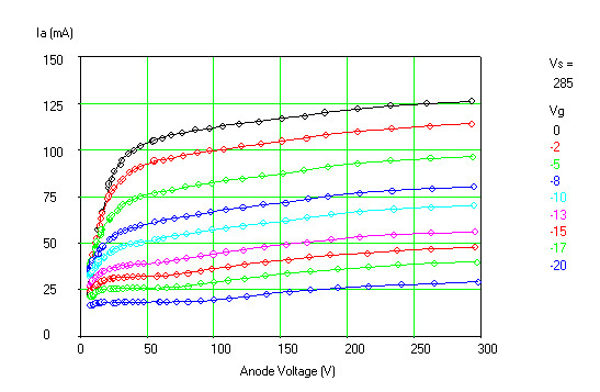
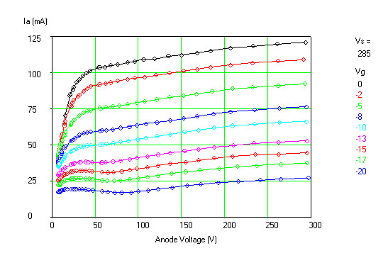
Starting to take care of these little gems of past technology, I begin to check the filaments. I test them with a tester to ensure they are not broken, and then power them with a bench power supply at constant current, at about half the voltage and current indicated on the datasheet. Then, slowly, I increase the voltage and current, getting closer and closer to the nominal values. I do this for a fairly simple reason... I gently awaken them from their slumber by gradually heating the filament without sudden surges of current that could damage it. Once at the rated values, I leave the filament on for 10-15 minutes, and then proceed with measurements of transconductance, mu, etc., etc. In short, without boring anyone, to summarize and simplify, I derive the graphs you see here for each individual tube and for each individual section.
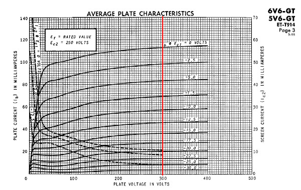
Looking at the two graphs of the two final 6V6 tubes, I already understand a lot about the history of this amplifier: it hasn't been used much! Both tubes are above the characteristics declared by the datasheet (this often happens with old tubes) and are in excellent condition. The 6V6 is a very robust tube, but like all tubes, it tends to wear out. What I notice is that they are not perfectly matched, but the 6V6-2 delivers a few milliamperes less than its (supposedly twin) sister. If this is completely inconsequential on a Class A amplifier for a Push-Pull, where the pair of tubes works in unison amplifying parts of the same sine wave, it's self-evident that a slight imbalance is generated, and therefore distortion and harmonics, etc., etc. The extent is negligible, and I do not intend to replace them (or match them better with others) until the end of the work, when, with an oscilloscope in hand, I will measure the extent of distortion produced, which I currently evaluate as very low.
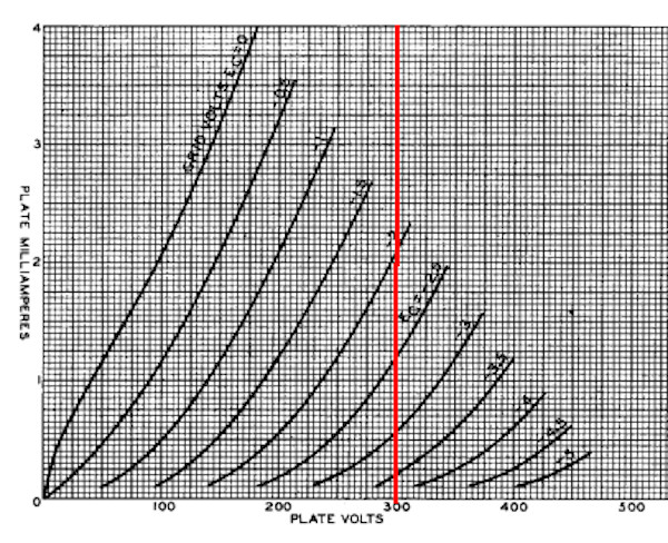
I've also included the datasheet graph for a quick comparison, on which I've drawn a red line at 300 volts, as my measurement's full scale is precisely 300 volts, which is the maximum voltage used in the amplifier.
12AT7 valve analysis
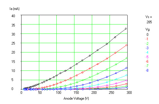
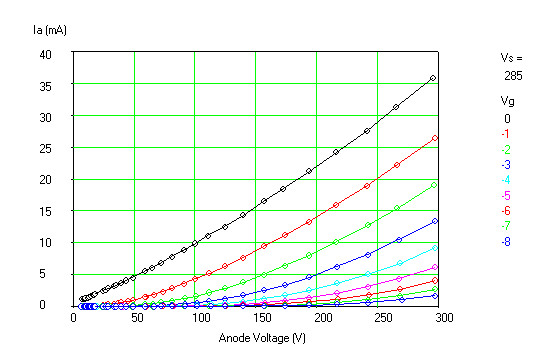
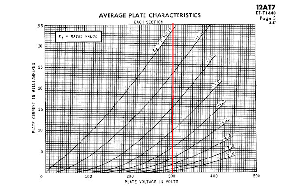
For completeness, I will also check the other two tubes, both double triodes and therefore with two sections. The last image relates to the datasheet graph, and here too, for quicker comparison, I have drawn the red line at 300v. This is the tube where one triode preamplifies the microphone and the second triode preamplifies the phono input and, clearly, the already preamplified microphone signal coming from the first triode.
Therefore, it is not necessary for the values to be identical... and indeed, there is a certain difference between the two sections. While the first is just a little lower than what is stated in the valve's datasheet, the second (like the two 6V6s) again exceeds the reported values. The difference in this case is, however, negligible and, in any event, completely irrelevant to the sound quality. From this, it can be seen that this valve, too, is in excellent health and has a long useful life expectancy.
Analysis of the 12AX7 vacuum tube
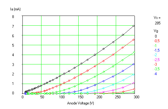
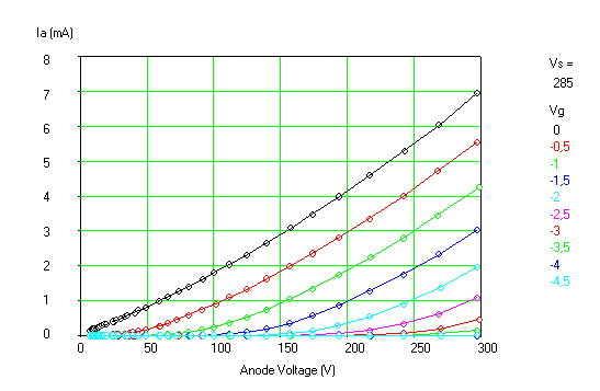
The 12AX7 valve is also a dual triode and, in this amplifier, an ECC83 Geloso is fitted, which is the perfect equivalent. Incidentally, the equivalent of the previous 12AT7 is the ECC82.
Moving on to the function of this double triode, as already mentioned, it is to drive the two output tubes, and therefore it is a phase inverter. The first triode will drive one 6V6 with the signal coming from the 12AX7, while the second triode will drive the second 6V6 but with the signal rotated by 180°. It is immediately noticeable that compared to the original graph there is a perfect correspondence (although at first glance they seem very different). Let's verify that on all the graphs, with a grid biased at -2 volts, the plate current is 2mA at 300 Volts. We also note that the two triodes of the tube are perfectly symmetrical, which is an excellent starting point, since this is where the two signals for the 6V6s originate… which will therefore be identical from the start.
Electronic control
At this point, the most expensive components of the entire machine have been cleaned and tested, and it's clear that there are no further obstacles to putting the apparatus back into operation. The question I often ask myself when working on any discarded object is: ‘Why didn't they use you anymore? Where did you break?’ And in fact, understanding whether it was a breakdown or simply abandonment can be useful for looking more closely at one detail rather than another.
From what I can see, it's evident that the asynchronous vibrator is damaged (even open) and the internal connecting wires are melted... so I'm sure something happened and it wasn't simple neglect. Yet the valves are perfect, the transformers are healthy... I haven't found signs of burning inside. Since it's a component that only functions with battery power, I'm keenly aware that I'll need to thoroughly check this section.
Now for the longest job... checking all the components, resistors, and capacitors, and the wiring. I don't hold out much hope for the capacitors, given the signs of moisture... I'm crossing my fingers for the resistors! Basically, it involves removing each individual component from the circuit and measuring and testing it on the bench. For electrolytic capacitors in particular, I check the insulation, ESR, actual value, etc.
I proceed
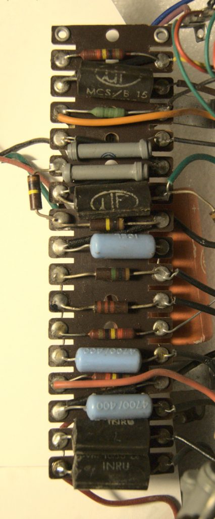
Needless to say, all the large electrolytic capacitors are gone... and even the small 25 uF 30V ones are no longer in working condition. On the perfboard, I proceed with a systematic check of all components, desoldering and measuring them. The resistors, even the precision ones, are all perfect. All the solder joints have been redone because: ‘there is no better way to mortify an amplifier than with a cold solder joint,” as I was told! Therefore, given the original solder joints (perfect to the eye), I preferred to redo them given their age and remembering the advice, I took special care with them... hot and well-made.
Recapping everything, I notice that the main switch is not original... in fact, this one has a single contact while originally it should have been double, interrupting both the electrical network and the battery. And indeed, the 12V cables were (poorly) bypassed. Yes... something happened in this section, and looking at the cables carrying the 12V, I see that they overheated in the past.
From all this, I deduce that the 200uF 25V electrolytic filter capacitor definitely shorted to ground (which is indeed how I found it out of spec), shunting the voltage to ground. In this way, a significant current passed through the asynchronous vibrator, damaging it, and the switch contact also failed... but the 10A fuse??? Who knows... perhaps it was replaced... I found it intact. In this way, however, all the current went to ground without damaging anything else.
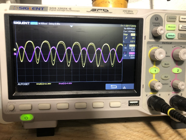
1st instrumental check
The fact is that everything has been checked and is efficient, the valves are excellent... the transformer... the capacitors replaced, etc., etc.! So?
2nd instrumental check 12AX7
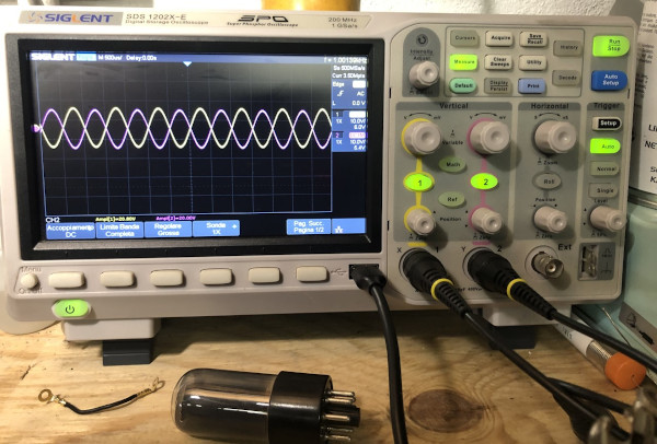
So, by positioning myself on the phase inverter (second triode of the 12AX7), I check the voltage that will drive the two 6V6s.
As seen in the image, the two 6V6s are well driven... the two lines (purple and yellow) are the two 1000 Hz tracks that will go to the respective grids of the 6V6s. We see them superimposed and 180° out of phase because this is the job the 12AX7 does to drive the two output tubes in push-pull.
So if everything here is correct, the problem is narrowed down to the power section.
Fatal! Sometimes a problem that takes a while to solve resolves itself... or rather... it sends you a clear signal... to seize immediately! In this case, it happened exactly like that... evidently this G221 really wanted to return to its former glory and, after reassembling the 6V6s to proceed with the checks, I powered up the circuit. After a couple of seconds (voltages in tube amplifiers rise slowly), I heard a barely audible crackling... click click... I immediately turned everything off!!
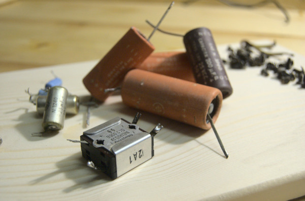
And him! And indeed, as I had written previously: “it must be changed regardless”; it's the selenium diode bridge! I look at it and immediately check the temperature… very hot… not normal for a few seconds of power! I caught it in time!! You can see it in the photo, in the foreground: B300 C70… on the side is the inscription 2A1.
Therefore, I'm replacing the selenium diode bridge with a silicon one, and I'll refer you to the technical section for a full explanation of why it shouldn't be left in and must be changed regardless, and how to do it! I calculate the voltage drop resistor… 220Ω for 2W and that's it… In the meantime, I also notice a loose connection between the output transformer's secondary and ground… it wasn't meant to be… I had to change all the screws! This particular one was the one that fastened one end of the transformer to the ground… it seemed well tightened, but clearly, the oxidized thread gave a false impression. I change the screw and tighten the terminal!
And here's a first test after installing the Bluetooth receiver. It's clear that you can't appreciate the audio quality, but at least it gives a precise idea of the work done and the progress made!
3rd instrument check
On the third check, everything returns to its place and the amplifier finally sounds again like a tube amplifier should sound.
I’m still detecting some distortion (clipping) at maximum volume, so I need to run a few more tests. However, as things stand now, with the volume set to 90%, everything is working exactly as the sacred texts teach, so I’m starting to use it on the test bench, leaving it on for several hours to verify the new diode bridge and, above all, the added resistor to compensate for the increased voltage. This, in fact, tends to generate heat (dissipating excess power as heat), but I need to verify that the temperature remains within acceptable limits for continuous use.
In the meantime, I realize that the restoration is nearing completion:
- I still need to fix the clipping (even if it's barely noticeable by ear, a tube amplifier can't and shouldn't remain like this!) ,
- I need to rebuild the missing microphone volume knob.
- I need to rebuild the voltage control knob, which is heavily damaged.
- Final intervention... I need to be able to connect a source for music, and not wanting to replace the phono or microphone jack, I decide to insert a Bluetooth module inside with an output jack for one of the two channels (using a pre-existing chassis hole) in order to pair it with its twin brother that I still need to restore, thus creating a usable stereo pair for everyday use!
And here is a video with the two devices connected and working!
The couple
As I mentioned at the beginning of this long article, the basic idea was to create a stereo pair, and after restoring the first one, I immediately started on the second amplifier. After installing the Bluetooth board in the first unit, I used an existing hole to install a connection jack. The whole setup works excellently.