TECHNICAL ARCHIVE · VALVE SOCKETS
← Find a valve socketEuropean Q seven-pin
Mechanical data, images and references from the EnryLab archive.
Key specifications
- Reference code
- EUROPEAN-Q7
- Contact positions
- 7
Mechanical dimensions
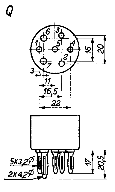
All linear dimensions are in millimetres and describe the valve base and its pins. They are not socket-hole diameters.
The pin circle passes through the pin centres. Pin spacing is the straight-line distance between adjacent centres. ≈ denotes a value calculated from nominal geometry; ± denotes a tolerance, parentheses show limits and ≤ denotes a maximum.
The contacts are not uniformly spaced. Dimension sets and variants are kept separate.
| Dimension | Value (mm) | Detail |
|---|---|---|
| Five smaller pins | ||
| Pin diameter | 3.2 | Dimension shown in the drawingView detail |
| Pin length | 17 | Dimension shown in the drawingView detail |
| Two larger pins | ||
| Pin diameter | 4.2 | Dimension shown in the drawingView detail |
| Pin length | 20.5 | Dimension shown in the drawingView detail |
| Valve base · Dimension set 3 | ||
| Lateral-pair centre spacing | 22 | Dimension shown in the drawingView detail |
| Axial-pair centre spacing | 20 | Dimension shown in the drawingView detail |
| Left-pair spacing (pins 6–7) | 16 | Dimension shown in the drawingView detail |
| Horizontal offset between pins 1 and 6 | 3 | Dimension shown in the drawingView detail |
| Horizontal distance between pins 1 and 5 | 11 | Dimension shown in the drawingView detail |
| Horizontal distance from pin 1 to pins 2–3 | 16.5 | Dimension shown in the drawingView detail |
In depth
European Q has seven asymmetrically arranged pins, with pin 5 in the centre. Five terminals are 3.2 mm in diameter and 17 mm long. The larger two, positions 6 and 7, are 4.2 mm in diameter and 20.5 mm long. Both diameter and length differences aid identification.
Pins 1 and 4 are 22 mm apart. Pair 2–3 has a vertical centre spacing of 20 mm, while pair 6–7 is spaced 16 mm apart. Seven does not describe a uniform division of a circle or a single spacing.
Horizontal dimensions complete the description: 11 mm from pin 1 to centre 5, 16.5 mm from pin 1 to the line through pins 2 and 3, and 3 mm from pin 1 to the line through pins 6 and 7. The last is a horizontal offset, not the straight-line distance between pins 1 and 6.
The dimensions have no verified tolerances. The correct view must be used when comparing base and socket, avoiding mirrored numbering. Male-terminal diameters and female-spring dimensions do not automatically coincide.
B7G, Septar and American seven-contact families retain their own geometries. Q's central contact is a physical position, not a universal electrical function. Its connection and those of the other pins depend on the valve.
Technical drawings
The drawings show orientation and geometry. Links beside the dimensions open the available detail.
Photos and examples
No photos are available for this socket yet.
Related valves in the archive
Total linked designations: 18
No related valves are available for this entry yet.