TECHNICAL ARCHIVE · VALVE SOCKETS
← Find a valve socketBritish 4-pin (B4)
Mechanical data, images and references from the EnryLab archive.
Key specifications
- Reference code
- BRITISH-B4
- Contact positions
- 4
Mechanical dimensions
All linear dimensions are in millimetres and describe the valve base and its pins. They are not socket-hole diameters.
The pin circle passes through the pin centres. Pin spacing is the straight-line distance between adjacent centres. ≈ denotes a value calculated from nominal geometry; ± denotes a tolerance, parentheses show limits and ≤ denotes a maximum.
The contacts are not uniformly spaced. Dimension sets and variants are kept separate.
| Dimension | Value (mm) | Detail |
|---|---|---|
| Valve base · Dimension set 1 | ||
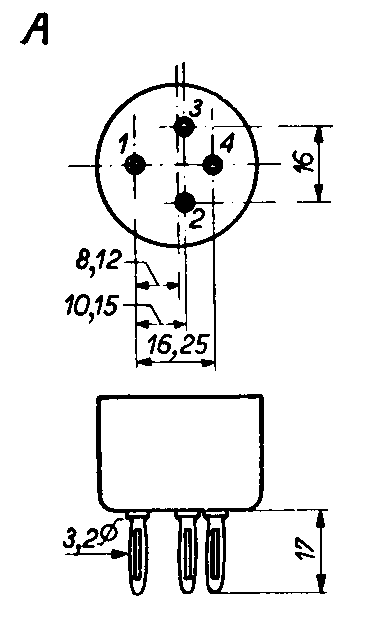
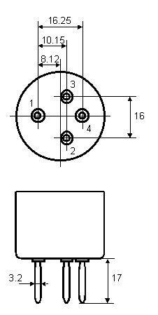
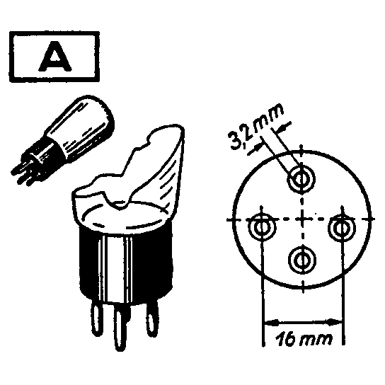
| Pin diameter | 3.2 | Dimension shown in the drawingView detail |
| Valve base · Dimension set 2 | ||
| Pin length | 17 | Dimension shown in the drawingView detail |
| Lateral-pair centre spacing | 16.25 | Dimension shown in the drawingView detail |
| Axial-pair centre spacing | 16 | Dimension shown in the drawingView detail |
| Valve base · Dimension set 3 | ||
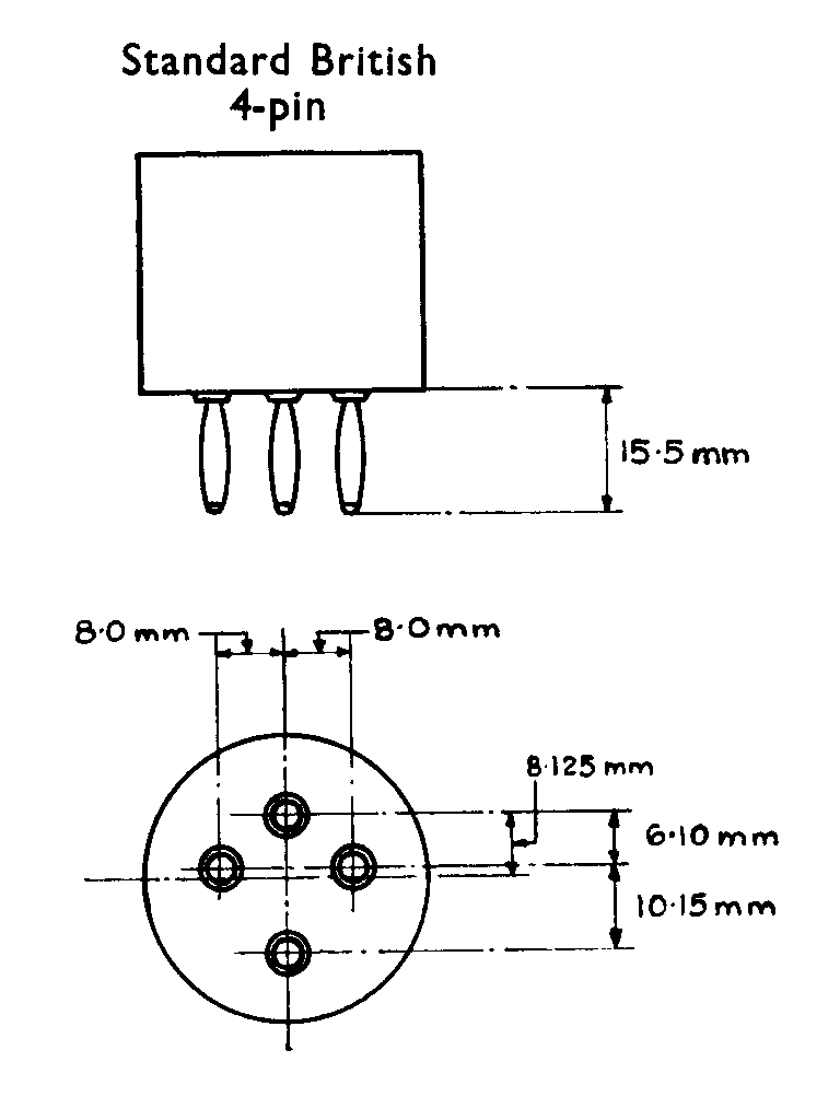
| Pin length | 15.5 | Dimension shown in the drawingView detail |
| Half the lateral centre spacing | 8 | Dimension shown in the drawingView detail |
| Axial offset B | 8.125 | Dimension shown in the drawingView detail |
| Axial offset C | 6.1 | Dimension shown in the drawingView detail |
| Axial offset D | 10.15 | Dimension shown in the drawingView detail |
In depth
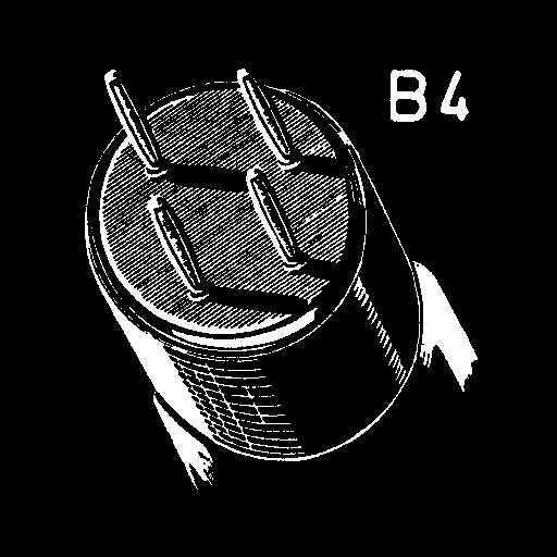
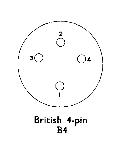
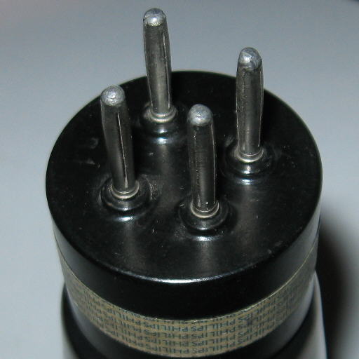
British B4 is a four-pin base with an asymmetric layout. Two contacts sit side by side, while the others occupy different positions along the base's axis. This geometry distinguishes the family from the general idea of a four-pin valve. It is not American UX4, nor is it automatically identical to every European four-contact construction.
B4's history is linked to the high-vacuum valve introduced in France in 1915 and the subsequent British R Type. The original layout assigned the anode to pin 1, the grid to pin 2 and the filament to pins 3 and 4. This is a historical arrangement, not a universal pinout: different numbering conventions also exist within the family.
Its construction history includes metal-shell and moulded bases, generally in Bakelite: unplated or plated brass versions, Marconi-Osram versions with a central groove, and moulded bases on later types. Particular variations include shortened filament pins on some Ediswan valves, the additional contacts of Nelson three-filament types and the side screw connected to the filament resistor on the Cossor Wuncell series. These variants require distinct mechanical descriptions.
The same care is needed with dimensions. Two drawings specify 3.2 mm pins, a length of 17 mm and 16.25 mm between the lateral pair; the other pair is given as 16 mm. The Standard British drawing instead specifies a length of 15.5 mm, lateral half-spacings of 8 mm and axial dimensions of 8.125, 6.10 and 10.15 mm. No declared tolerance is available that would justify treating all these measurements as one equivalent set.
The dimensional description therefore keeps these observations separate by drawing. No pin circle diameter or uniform adjacent-pin spacing is assigned to the family: the layout is irregular and those fields would be misleading. Pin diameter, distances within the same view and comparison with the illustrated variant are more useful for identification. Even the insulating body's diameter cannot be obtained by measuring pixels in an image without a reliable scale.
Some valves add a side or top terminal while retaining the four-contact lower interface. An external connection does not automatically become a fifth B4 position. The GPO specifications for CV1636 and CV1637 provide an instructive example: both refer to the LS5 prototype, but require B4 and bayonet BC4 respectively. A common prototype or electrical relationship therefore does not cancel an explicitly different base.
PX4, PM2 and L410 are associated with this family. They help place it in context, but do not replace examination of the individual construction. Mechanical selection or dimensional searching requires the variant to be retained; wiring and electrical use still require the data for the individual valve.
Technical drawings
The drawings show orientation and geometry. Links beside the dimensions open the available detail.
Photos and examples
Related valves in the archive
Total linked designations: 6,644